


 SMT Prospects and Perspectives: AI Opportunities, Challenges, and Possibilities, Part 1
 Nolan’s Notes: Do More, Get More
 Global Sourcing Spotlight: Don’t Be Afraid of Global Sourcing
Part 1: The French Rework Connection
December 31, 1969 |Estimated reading time: 10 minutes
Two companies join hands across the ocean to develop a universal method of verifying all types of rework equipment.
By Julien Ratie, Emmanuel Smague, Philippe Raout and Mike Hayward
When the French division of an international EMS company* needed to solve a growing problem in its rework cell, it discovered that the type of tool needed to solve the problem did not exist. The EMS company has six rework systems, comprised of five hot air/convection systems and one laser system, each used for specific rework needs of different product configurations, materials and components. The company began experiencing process drift in one of the machines that could not be pinpointed or controlled. It was not overly serious, but could lead to future quality issues if not corrected. Either the heat transfer rate or process time was off, but the problem was that without really knowing the source, there was no way of knowing whether this was being caused by true machine drift or recipe errors being programmed into the machine.
After upgrading parts and performing general maintenance, the rework machine was still drifting. To pinpoint the source, the next step was to try to profile the static rework process to get a handle on what the machine was doing over time.
Engineers at the EMS company designed and built model pallets that would sense all the elements in the rework machine, top and bottom of the active working platform and heating elements, with an eye on how it would interface with all the company's different rework machines, not just one particular model. This was done first using a printed circuit board (PCB) populated with specific components, including ball grid arrays (BGA) and quad flat packages (QFP) common to most assemblies the company builds.
 Figure 1. Using an FR4 board, repeated exposure to the heat of rework caused the board to delaminate, the QFPs to deteriorate and the thermocouples to lift.
The board was wired with thermocouples in all critical areas: air top, air bottom, mass bottom, mass top, PCB surface bottom and PCB surface top. The thermocouples were plugged into a standard thermal profiling device to record the sensed temperature data.
This worked well for a few tests, but repeated exposure to the heat of rework caused the board to delaminate, the QFPs to deteriorate and the thermocouples to lift (Figure 1). These issues caused faulty data readings. Unless there was a ready supply of these sacrificial test boards — each exactly the same, which is almost impossible to guarantee — there was no way any real drift could be measured accurately or the efficiency of the rework equipment. The test board introduced too many errors of its own.
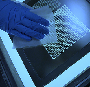
 Figure 2. A stainless steel test pallet provided durability, but the pallet itself did not parallel the real heating exchange rate of a PCB. The thermocouple wires shown lead back to a data recorder device (profiler).
Next, the EMS engineers built a test assembly pallet using a stainless steel platform instead of FR4 material (Figure 2). This provided durability, but the pallet itself did not properly parallel the real heating exchange rate of a PCB. Because it did a fairly stable job of measuring only the basic reproducibility of the rework machine itself, this was used in the interim. However, what was necessary was to create the equivalent of a reflow oven or wavesolder "machine quality management" (MQM) tool. Both types of process qualification MQMs are used at the EMS company to validate and verify its ovens and wave machines on a regular basis. This new tool had to do what the other MQMs did, but have qualities and a configuration different from them. It had to specifically suit the rework process and work with all types of rework equipment.
Creating a Roadmap
The engineers at the EMS company developed the project description, with the goal of teaming with an outside source knowledgeable in this specific type of technology. To avoid false starts, the plan, titled "Project SPC Repair," had to be as detailed as possible, covering every aspect of the different types of in-house rework machines, such as their individual functions and idiosyncrasies (Figures 3 and 4). The most important issue was that regardless of the type of rework machine used, the final MQM tool developed had to address all universal rework process stages, such as:
- Preheat area. This step preheats both the machine and the PCB. The duration of this step is not programmable data. It is only after the validation of a temperature condition (machine and PCB) that the program moves to the next step. This step is necessary to minimize the impact of the initial conditions.
- Soak area. This step raises all the component areas to a certain temperature (t<183°C). The timing of this step is programmable data.
- Reflow area. This is the time the component is held at liquidus (t>183°C). The reflow is a programmable data step.
 Figure 3. Graphic display of the required process data as defined in the 'Project SPC Repair' document.
With their detailed set of specifications in hand, the EMS company approached the vendor company** that had designed the reflow and wave MQMs they used. The vendor already had knowledge in the areas of materials, tooling and software for this product type. The specifications and what new goals a product of this type had to meet were supplied. The EMS company also would serve as the beta test site and team with the vendor company to work through problems as the product went through development stages.
 Figure 4. Recommendations for MQM rework tool as defined in 'Project SPC Repair' document for dimensions.
Designing the initial tool went through several iterations, but the key structural elements that evolved included composite delmat material (CDM), which was selected for the basic pallet on the new rework MQM. CDM is stable under thermal stress, can withstand thousands of cycles, and will not delaminate or degrade. The pallet measured 6 mm thick, and the pallet size was set at 200 × 254 mm, which made it fit universally across all rework platforms. An edge profile of 2 mm was machined around all four sides to make the tool fit into a work holder. Machining a handle into the pallet to make lifting and placing easier was another idea. Ruler markings were screened on topside edges to help in setup. Standoff pillars were added to all corners, top and bottom, to protect the sensors to be added.
After the vendor completed the basic platform design, they needed to find sensors that would measure the required parameters. Like the rework and wavesolder MQM tools, this was to be an "all in one" tool with pallet, sensors and a section to both hold and protect a data logging profile device. Everything had to be built into the pallet for years of rugged use, and the information had to be delivered as if it were actual parts under rework; a slightly different challenge than sensors passing through an active reflow or wavesoldering process.
Road Test
To recreate a part under rework conditions, the vendor company found a special type of sensor that emulates the actual temperatures that a BGA would experience in production (Figure 5). The sensor is manufactured out of a single piece of stainless steel foil, and a thermocouple is bonded or hot tip welded to it. Then the device is encased in a stainless steel frame. The whole sensor is less than 3 mm thick. This was attached to the top of the pallet with a zero mass thermocouple bonded next to it. A duplicate sensor/thermocouple configuration also was attached to the bottom side of the pallet.
 Figure 5. Special sensor that emulates the actual temperatures that a BGA would experience in production. It is configured on both sides of the rework MQM tool pallet.
In operation, the pallet is placed on the rework station table and a nozzle comes down, enclosing the top sensors (Figure 6). The second sensor assembly, mounted underneath the pallet, detects heat energy from the bottom, since most rework machines have a heating element underneath to minimize temperature differentials on the board that potentially could absorb the energy intended for the device under rework.
 Figure 6. The rework MQM tool in use on a rework machine at the EMS company. The main sensor acts as a component in rework and sends all temperature data back to the integral data logger located on the rework MQM pallet in a protective shield.
Now that there was a good working prototype, beta testing began. Tests were designed to simulate variations in rework machine parameters and included adjustments — both positive and negative — around a set of nominal values. First, a nominal capability study of 25 cycles was conducted to make sure that both the machine and pallet were statistically under control. After it passed this capability study, an on-the-floor test plan involving 28 different variations to parameters was conducted over a period of several months. Each test was conducted three times to increase confidence in the results; 84 experiments in total covered three major categories.
- Stabilization Cycle Parameters. These occur in the preheat stage. Preheat normalizes the assembly and preconditions it for soak and peak stages. This set of tests involved moving the positions of the trigger thermocouples and varying the programmed trigger temperature values about the nominal values. In all cases, the pallet detected the variations.
- Soak Cycle Parameters. Following preheat, the cycle continues with a soak phase where more energy is applied so that components are raised in temperature at a higher rate. Variations were made to both top- and bottom-side heaters in stages of ±7°C and ±15°C. This set of parameters yielded some interesting results that recommended changes to the bottom-side air sensor of the MQM. Although the pallet was successfully detecting the variation induced at both ±7°C and ±15°C, it was felt that improvements could be made to make these more prominent. Topside performance was as expected. Additional experiments were conducted with adjustments to the cycle times being made. The pallet detected all such variations.
- Reflow Cycle Parameter. The final stage of the cycle is to bring the device up to its maximum temperatures, simulating solder reflow. This set of experiments cloned those of the preheat cycle with the same results.
Conclusion
With all the basic process parameters achieved, the EMS company currently is using its new universal rework MQM tool for troubleshooting and diagnostic characterization of all its rework machines (Figure 7). The emphasis during this period also is directed to the interpretation and fault diagnosis area of the software package. Although current software is providing what was requested, there is more progress to be made. Just the process of using the tool and software on a regular basis has stimulated many new ideas and a "wish list" to incorporate more unique features, and the EMS company wants to delve more deeply into serious SPC analysis areas. The EMS and vendor are continuing a partnership to work on the evolution of this unique MQM, addressing these features.
 Figure 7. A characterization profile from a rework machine. The universal rework MQM tool is used for troubleshooting and diagnostic characterization of all rework machines at the EMS company.
Complex board configurations, small surface mount devices and lead-free solders are only a few issues making rework both difficult and imperative to precisely control. Now there is a reliable way to validate and verify rework equipment for optimum capability. This not only saves time and adds to overall line control, but also is beneficial to show customers. Even minimal rework is a part of production and, as such, must be controlled as tightly as every other process step. The next step is to expand by integrating rework data into more detailed SPC production analysis and perhaps beyond.
*Solectron Corp., Bordeaux, France** Electronic Controls Design Inc. (ECD)
Julien Ratie, process technician, may be contacted at JulienRatie@FR.SLR.COM; Emmanuel Smague, process engineer, may be contacted at EmmanuelSmague@FR.SLR.com; Philippe Raout, process engineer, may be contacted at PhilippeRaout@FR.SLR.com; Mike Hayward, managing director, may be contacted at mike.hayward@ecd.com.
Look for Part 2 of this article on SMT Online, www.smtmag.com, in mid-April.
Share on:


