-

- News
- Books
Featured Books
- smt007 Magazine
Latest Issues
Current Issue
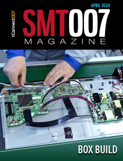
Box Build
One trend is to add box build and final assembly to your product offering. In this issue, we explore the opportunities and risks of adding system assembly to your service portfolio.

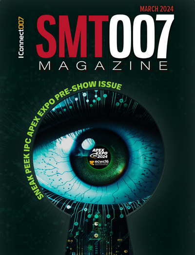
IPC APEX EXPO 2024 Pre-show
This month’s issue devotes its pages to a comprehensive preview of the IPC APEX EXPO 2024 event. Whether your role is technical or business, if you're new-to-the-industry or seasoned veteran, you'll find value throughout this program.

Boost Your Sales
Every part of your business can be evaluated as a process, including your sales funnel. Optimizing your selling process requires a coordinated effort between marketing and sales. In this issue, industry experts in marketing and sales offer their best advice on how to boost your sales efforts.
- Articles
- Columns
Search Console
- Links
- Events
||| MENU - smt007 Magazine
Reflow Profiling on the Electrical Reliability of No-Clean Solder Paste Flux Residues
May 5, 2015 | By Eric Bastow, Indium Corp.Estimated reading time: 2 minutes
An estimated 80% of all SMT assembly in the world is performed with a no-clean soldering process, largely due to the predominance of consumer electronics. The continuing trend of increasing miniaturization that dominates modern electronics devices requires no-clean flux residues to be as benign and electrically resistive as possible. Solder pastes with an IPC J-STD-004[1] classification of ROL0 or ROL1 rely heavily on two basic mechanisms to render the flux residue as "no-clean": (1) the encapsulating properties that the rosin provides and (2) the heat activation/decomposition of the chemicals in the flux, commonly known as “activators.” The latter is generally known in the industry, but is rarely taken into consideration for reflow profiling in SMT assembly.
Optimization of a reflow profile often focuses on mitigating defects such as voiding, tombstoning, graping, slumping/bridging, etc. However, little thought is given to the reflow profile’s effect on the electrical reliability of the no-clean flux residue. Because of the wide variation in size and thermal density of SMT components and PCBs, achieving a reflow profile that equally heats the entire assembly can be challenging and often impossible. The temperature under a large component, such as a BGA, is often markedly cooler than a smaller component, such as a passive resistor or capacitor. This paper will discuss an experiment that studied the effect of reflow profiling on the electrical reliability of no-clean flux residues that can be measured using IPC J-STD-004[1] surface insulation resistance (SIR) testing. Both a halogen-free (ROL0) and a halogen-containing (ROL1) Pb-free no-clean solder paste, exposed to various reflow profiles, were used in this study.
Prior work had exposed the impact on SIR values of entrapping a solder paste flux residue under a component body or RF shield. What was unclear in that work is the impact of the reflow profile. Invariably, flux underneath a device does not get exposed to the same heat that an exposed flux does. So performing an experiment that focused solely on the effect of heating seemed pertinent.
Experimental
In this experiment, a total of eight reflow profiles were used for each solder paste; one paste being ROL0 and the other being ROL1. Both solder pastes used are standard commercially available products. All boards were reflowed in a standard convection belt furnace type reflow oven with an air environment. The reflow profiles consisted of four different peak temperatures: 225°C, 235°C, 245°C and 255°C.
For each peak temperature, reflow profiles representing a "ramp to peak" and "soak" profile were created. The purpose of creating both a ramp to peak and a soak profile was to see if and how, not only the peak temperature, but also the “shape” of the profile, has an impact on SIR performance. For the sake of this work, the “soak” is defined as the period during which the PCB is between 200°C and 215°C.
Editor's Note: This article originally appeared in the April issue of SMT Magazine.
Suggested Items
Hentec/RPS Publishes an Essential Guide to Selective Soldering Processing Tech Paper
04/17/2024 | Hentec Industries/RPS AutomationHentec Industries/RPS Automation, a leading manufacturer of selective soldering, lead tinning and solderability test equipment, announces that it has published a technical paper describing the critical process parameters that need to be optimized to ensure optimal results and guarantee the utmost in end-product quality.
Empowering Electronics Assembly: Introducing ALPHA Innolot MXE Alloy
04/16/2024 | MacDermid Alpha Electronics SolutionsIn the rapidly evolving electronics industry, where innovation drives progress, MacDermid Alpha Electronics Solutions is committed to setting a new standard. Today, we are pleased to introduce ALPHA Innolot MXE, a revolutionary alloy meticulously engineered to address the critical needs of enhanced reliability and performance in modern electronic assemblies.
Inkjet Solder Mask ‘Has Arrived’
04/10/2024 | Pete Starkey, I-Connect007I was delighted to be invited to attend an interactive webinar entitled “Solder Mask Coating Made Easy with Additive Manufacturing,” hosted by SUSS MicroTec Netherlands in Eindhoven. The webinar was introduced and moderated by André Bodegom, managing director at Adeon Technologies, and the speakers were Mariana Van Dam, senior product manager PCB imaging solutions at AGFA in Belgium; Ashley Steers, sales manager at Electra Polymers in the UK; and Dr. Luca Gautero, product manager at SUSS MicroTec Netherlands.
TE Connectivity Orders Hentec Industries/RPS Automation Pulsar Solderability Testing System
04/09/2024 | Hentec Industries/RPS AutomationHentec Industries/RPS Automation, a leading manufacturer of selective soldering, lead tinning and solderability test equipment, is pleased to announce that TE Connectivity has finalized the purchase of a Pulsar solderability testing system.
Indium to Host Free Webinar on Lead-Free Solder Paste for Automotive Applications
04/09/2024 | Indium CorporationIndium Corporation’s Senior Research Metallurgist, Jie Geng, Ph.D., will conduct a webinar on low-voiding, high-reliability, lead-free solder paste for automotive applications.


