


 Global Sourcing Spotlight: Golf, Friedman, and the Benefits of Global Sourcing
 Nolan’s Notes: Coming to Terms With AI
 The Knowledge Base: A CM’s Perspective on Box Build Practices
A New Approach to Vapor Phase Reflow Soldering
December 31, 1969 |Estimated reading time: 8 minutes
The introduction of lead-free soldering processes has generated renewed interest in vapor phase reflow soldering for thermally challenging PCBAs. Although vapor phase soldering - also called condensation soldering - has been in use since the mid-1970s, there have been no significant advancements in its practical application until now. This article reviews the process, and describes a new method of vapor phase soldering.
By John Bashe, REHM USA
The introduction of lead-free soldering processes in the electronics assembly industry has generated renewed interest in vapor phase soldering for thermally challenging PCB assemblies (PCBAs). Although vapor phase soldering - also called condensation soldering - has been in use since the mid-1970s, there have been no significant advancements in the practical application of this technology until recently. A technology based on an injection principle was introduced to address the limitations of traditional vapor phase soldering systems. This method allows the user to carefully control the volume of the soldering medium (vapor), while reflow soldering PCBAs inside a hermetically sealed chamber. This offers a greater degree of control and flexibility of the reflow soldering profile than previously possible with existing vapor phase systems. This concept also reduces operating costs associated with vapor phase systems, which historically have been expensive to operate and maintain.
Patented in 1975 by C. Pfahl and H.H. Ammannin, vapor phase soldering is one of the oldest reflow soldering processes. With vapor phase soldering, latent heat is released during the change of state from a vapor to a liquid (i.e. condensation). This heat is used to heat the assembly group. During the change of the medium, a large amount of heat is released - leading to a rapid temperature increase of the assembly group. For the vapor phase soldering process, the coefficient of heat transfer (h) is on the order of 300 W/m²K, while for forced convection soldering (air or nitrogen), values typically are smaller by a factor of 10. The temperature always remains constant during the change of state of the medium (phase transition), which occurs on the surface of the PCBA. This results in uniform heating of the assembly, regardless of board shape or layout. However, due to the high rate of heat transfer, care must be taken to ensure the heating gradients do not exceed the recommendations of the solder paste and component suppliers - typically in the range of 2-3°C/sec. max. By selecting a fluid with the appropriate boiling point, peak temperatures of the PCB and components can be controlled within small tolerances. This small ΔT is an advantage of the vapor phase process, especially for lead-free soldering, which typically requires a smaller process window. The risk of overheating components is also eliminated because the temperature of the PCB and components cannot exceed the boiling point of the soldering fluid selected. Finally, because the soldering fluid used in the process is inert, the need to use nitrogen for inert-atmosphere soldering is eliminated. These are the three primary advantages of the vapor phase soldering process, when compared to forced convection reflow ovens. However, it should be noted that forced convection soldering is still the process of choice for high-volume production of less thermally challenging assemblies.
Traditional Vapor Phase Soldering
Until now, all vapor phase soldering systems have been based on a vertical tank concept. In a tank, an appropriate fluid is brought to a boil - creating a vapor cover over the liquid. The PCBA to be soldered is lowered into the vapor cover, and the vapor condensates quickly onto the cooler surface of the PCB and components. The condensation rate cannot be controlled easily at this point; the PCBA heats up according to natural circumstances. It is not possible to influence the heating gradient. Controlling heating (and cooling) gradients during the reflow process is limited with the vertical concept.
In the past, different solutions to the problem of the influence of the heating gradient were implemented. Often, additional heating zones are arranged before the vapor zone, which provides for pre-heating of the assembly group by means of radiation or convection. The disadvantage is that in the decisive (peak) solder phase, the temperature variation cannot be influenced significantly. If IR (radiant) heating is used during the pre-heat phase, less-than-uniform heating can occur, resulting in significant temperature differences between components prior to reflow.
 Figure 1. Progressive dipping into the vapor cover. The area outlined in red shows the available vapor volume.
Another solution to control temperature gradients during the reflow process is a successive, vertical dipping of the assembly group into the vapor. The deeper the assembly group is dipped into the vapor cover, the more vapor can be provided (Figure 1). With this procedure, it is not taken into account that the vapor, which is a gas, cannot have a uniform (i.e. flat) interface with the surrounding atmosphere.
Dipping the assembly group into the vapor cover can generate turbulence, and cause the vapor to intermix partially with the surrounding air. On one hand, this leads to an unpredictable volume of condensation vapor; on the other hand, the condensation temperature of the vapor can change based on the partial pressure curve of the mixed air. This process is limited in its ability to generate reproducible temperature variations. The reciprocating motion of the assembly group prior to reflow is also undesirable. Limitations of traditional vapor phase technology are:
• Limited ability to control temperature gradients during the reflow process,
• Vertical transport of the PCB is difficult to adapt to an inline process,
• Vertical movement of the PCBA prior to reflow,
• High operating costs due to consumption (evaporative loss) of soldering medium,
• Difficult to integrate for vacuum (void-free) soldering process.
The Injection Method
The injection method was developed to address the limitations of the vertical tank concept. Assemblies are transported using a horizontal conveyor into a process chamber, which is then hermetically sealed. The floor and sidewalls of the chamber contain heating elements that bring the surfaces to a pre-programmed temperature. A defined volume of the fluid medium Perfluorpolyether is injected into the process chamber. When the fluid comes in contact with chamber surfaces, it boils and creates a vapor cloud. By metering the volume of fluid injected into the chamber, the heating gradient can be controlled and adjusted based on the thermal characteristics of each PCBA. The rate of heating is proportional to the volume of vapor in the chamber (Figure 2). By extracting a portion of the vapor from the chamber during the process (using a vacuum pump) it is also possible to reduce the heating gradient prior to reflow to create different types of profiles (saddle vs. linear profile). The rate of vapor extraction after reflow is also programmable to control the cooling gradient, which typically should be in the range of 2-3°C/sec. Extracted vapor is re-condensed, filtered for flux removal, and returned to a storage tank. Cycle times for this entire process are similar to that of convection reflow ovens. This process also is compatible with commercially available tin/lead and lead-free solder pastes. The Perflouropolyether fluid is available in various grades, with boiling points between 210-260°C, depending on process requirements.
 Figure 2. Influencing of temperature profiling through medium injection (Ts=230°C).
Traditionally, most vapor phase soldering has been performed on a low-volume batch basis. Systems based on the injection principle are available in a batch configuration for this type of manufacturing; however, because it uses a horizontal transport system, it is easy to adapt this technology to higher-volume inline production. Inline systems can feature either single or dual-lane conveyors. For inline systems, multiple PCBs are collected on an input conveyor and transported simultaneously into the process chamber. The number of PCBs in the chamber at one time is a function of board length. When the reflow process is completed, soldered PCBs are transported to an exit conveyor, where they are cooled to a safe handling temperature prior to transport to the next process (Figure 3).
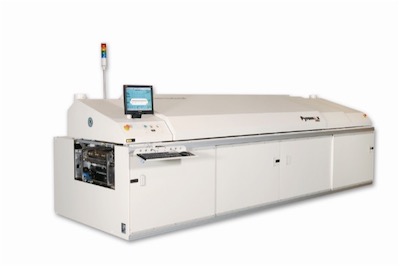
 Figure 3. Injection-based inline vapor phase soldering system.
null
Vacuum Soldering
Vapor phase systems offer the optional ability to produce a vacuum after soldering to remove voids from the molten solder joint. Because injection-based vapor phase systems use a sealed chamber during the soldering process, it is simple to integrate a vacuum option into the process. Good void-free solder joints can be achieved with a vacuum under pressure of <20 mbar. This can be especially useful when manufacturing assemblies for high-power applications where efficient heat transfer from components to the board is critical. Eliminating significant voids in solder joints ensures that these assemblies will perform reliably.
A vacuum can be applied in a fixed or variable level. A variable vacuum can allow large voids to migrate gradually to the perimeter of the solder pad, preventing the possibility of solder splatter. During the soldering and vacuum process, the assembly is stationary inside the sealed process chamber. Traditional systems based on the vertical tank concept require the PCB to be transported vertically during the liquidus phase to an overhead cover, creating a sealed chamber before applying the vacuum. Movement of the assembly prior to completion of reflow is undesirable, and this extra step also adds cycle time to the overall process.
Cost of Ownership Considerations
Vapor phase systems’ several inherent cost advantages over convection reflow systems include lower power consumption (typically 5-7 kW) and the elimination of nitrogen for inert atmosphere soldering.
Historically, the high operating costs of a vapor phase system have been attributed to the loss of soldering fluid due to evaporation, and incomplete drying of the PCB after reflow. Injection-based systems are closed loop, which prevents the vapor from escaping to the surrounding environment. Therefore, these systems have a low rate of consumption, typically in the range of 1-1.5 gm of fluid per cycle.
Based on an estimated cost of $650/gallon for the required Perfluorpolyether fluid (6,850 grams/gallon), this results in a cost of about $0.10 per reflow cycle. Because the fluid is inert and non-toxic, waste disposal costs are also minimized. Maintenance requirements for cleaning the system are minimized because flux residues are extracted with the vapor on completion of each cycle. The process chamber is not continuously filled with fluid; therefore, it can be easily cleaned periodically, as required.
Conclusion
Due to its heat-transfer characteristics, vapor phase reflow soldering is best suited for soldering high-mass, thermally challenging assemblies. The implementation of lead-free soldering requires a smaller process window, which can best be achieved by using the vapor phase soldering process. Recent advances in vapor phase soldering technology have resulted in increased flexibility of the process, and reduced operating costs.
John Bashe, general manager, REHM USA LLC, may be contacted at (770) 797-3024; e-mail: jbashe@rehmusa.com.
Share on:


