


 Global Sourcing Spotlight: Golf, Friedman, and the Benefits of Global Sourcing
 Nolan’s Notes: Coming to Terms With AI
 The Knowledge Base: A CM’s Perspective on Box Build Practices
X-Ray Inspection in the Third Dimension with Oblique Viewing Technology
December 31, 1969 |Estimated reading time: 8 minutes
Consumer demand is driving the evolution of miniaturized electronics products. As a result, SMT circuitry is being compressed onto smaller substrates with higher numbers of interconnects, for less cost. To maintain quality, manufacturers have resorted to sophisticated X-ray inspection technologies, especially for BGA and µBGA components.
By Jon Dupree
For such "hidden" interconnects, X-ray microscopy has been a successful inspection and analysis tool. Until recently, microfocus X-ray systems have been limited to two predominant approaches. The first uses real-time, 2-D X-ray microscopy, otherwise known as radioscopy, with manipulators for positioning samples (the objects being viewed) along five axes, including tilt and rotation.
 Figure 1. The center image displays BGA balls with clear voids, as shown in a top-down view. When looking at the oblique images shown around the perimeter, each angle provides different information on the location of the voids.
null
The other technique is 3-D imaging technology, namely laminography or tomosynthesis, to generate image slices of the solder ball. The 3-D systems gather multiple oblique images of the sample to construct a rendering of X, Y and Z planes. Laminography systems excel in identifying solder and component-related defects in both single-and double-sided boards. These systems are used in production environments with high product complexity and volume. However, due to the nature of the underlying technology and the use of sealed tubes, geometric magnification is limited, programming time is extensive, and the systems' real-time viewing capabilities are limited.
This article focuses on X-ray radioscopy, in particular oblique viewing, which has advanced from conventional manipulation of the sample to a more sophisticated and effective method known as auto isocentric motion (AIM). AIM is intended for production applications where quick, easy identification of production line defects, such as missing solder balls, cracks in joints, solder voids and shorts, etc. is required. Oblique viewing also applies to in-depth failure analysis. For precise inspection in laboratory applications, a "conical target" enables oblique viewing of a defect from the best possible angle.
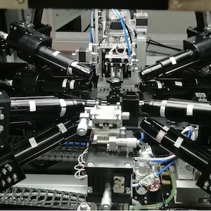
 Figure 2. The most effective means of obtaining an oblique-angle 2-D view is by using a 2-D X-ray inspection system, which features an image intensifier that can rotate 360° and tilt 60° to capture images from any angle.
null
Conventional Radioscopic Systems
Real-time 2-D X-ray systems test single-sided assemblies using geometric magnification to provide a microscopic view of the sample. Geometric magnification of an image is directly related to the distance between the sample and the focal spot of the X-ray tube. Geometric magnification is an exponential factor, so high magnification can only be achieved when the sample is close to the focal spot. Magnification over 100X typically occurs below the 5 mm of distance from the focal spot.
Manipulating an assembly for oblique viewing enhances inspection of both single- and double-sided assemblies. Sample manipulation and orientation typically are achieved with a joystick and viewing window. At high magnifications, the operator must be familiar with the responsiveness of the joystick, as well as the manipulator speed, and must be able to judge how close the sample is to the X-ray tube to avoid collision and potential damage to the sample. The operator also must be able to discern between bottom-side board elements and actual solder and component defects. Certain solder-related defects, such as misalignment, solder shorts, over- or undersized solder connections, and missing balls, are easily identified by traditional 2-D systems, but defects such as opens, insufficient solders, or defects mirrored by bottom-side devices require oblique viewing.
To view the details at an angle, conventional systems tilt the sample for an oblique view. Unfortunately, the highest magnifications cannot be achieved because the area of interest tilts away from the focal spot. Since X-rays typically are transmitted in a conical fashion from the source, some systems shift the image intensifier along one axis to obtain a highly magnified oblique view. The sample stays flat and close to the focal spot, and the image intensifier captures the X-rays from the edges of the transmission cone. Due to the mechanical design of a sealed tube, the transmission cone is limited to about 53°, so the oblique viewing angle is slight. An open tube has a 170° conical beam, as well as an end window focal spot. High magnification oblique views created by moving the detector only are effective using an open tube with this type of focal spot. This type of oblique viewing is effective as long as the best view lies along the axis of the detector shift. However, when searching for voids or opens, a view from one angle may show precise location, while a view from the other could hide the defect.
AIM Systems
AIM technology was developed in response to requests from engineers for images similar to those produced by 3-D CAD (computer-aided design) systems, where they could visually "circle" around an object to see it in three dimensions. In other words, this is the same oblique viewing concept as 3-D systems, but with the movements viewed in real time. The need also arose for higher resolution, higher magnification and increased clarity to ease image interpretation. AIM technology keeps the region of interest (the area being X-rayed) continuously within the field of view as the sample or imaging chain is rotated. As implemented in 2-D X-ray inspection systems, AIM technology allows the user a real-time glimpse into the third dimension of packages (Figure 1).
The X-ray detector is mounted on a proprietary curved guide that allows it to move from zero to 60° off-axis. The guide is placed atop a rotational pivot, permitting a full 360° of rotation (Figure 2). The detector then is able to stop anywhere along this dome of motion, and maintains a constant distance from the X-ray source. This ensures minimal image distortion at oblique angles, a common problem if the detector is not angled properly and the focal-spot-to-detector distance is not constant. When the detector is in the center of this dome of inspection, X-rays are gathered from the center of the X-ray cone. When the detector shifts, X-rays are gathered from the outside edges of the cone. When the detector is moved along the dome of inspection, the viewing line is shifted in the X and Y dimensions of the sample. AIM technology makes use of sophisticated algorithms to compute the necessary manipulator adjustments to keep the region of interest in the viewing line at all times (Figure 3).
With AIM technology, the user can view many flaws undetectable with other 2-D X-ray approaches, such as solder opens, insufficients and poor wetting. But these sharp, intricate views of the sample are only part of the AIM advantage. AIM is largely system-driven, so all operations can be performed with a mouse click. The user needs only to focus on the X-ray image without monitoring the sample position.
 Figure 3. Traditional radioscopic X-ray systems differ from those using AIM technology, in that the technology continuously maintains the region of interest (ROI) within the field of view.
null
AIM technology, properly partnered with other advanced system and software features, meets a wide range of application and industry needs. An AIM-powered system is recommended for any part with multiple layers that are difficult and time-consuming to inspect with traditional systems. Examples include double-sided boards, especially back-to-back ball grid arrays with BGA devices on either side of a board; multi-chip components in which the chips are stacked on top of each other inside a package; components that require underfill or encapsulation, typically flip chip devices, requiring inspection of each interconnection for voids; filled and plated vias; and press-fit connectors.
 Figure 4. Advanced oblique viewing for in-depth failure analysis is possible through use of a Conical Target, which allows the sample to tilt up to 70° without contacting the edge of the tube, while the focal spot stays in close proximity to the area of interest.
null
As X-ray resolution has improved past the 1 µm barrier, a limitation has been recognized for oblique views that depend on shifting the detector. X-rays on the outer edge of the transmission cone lose intensity. Also, the X-ray waves are slightly distorted along the edge of the cone, so the image from a tilted detector is not as "true" as an image when the detector is perpendicular to the center beam of the X-ray. With 2 µm and larger resolutions, the distortion is hardly noticeable, as long as the distance from the focal spot to the detector is consistent, and the detector plane is perpendicular to the travel of the X-ray. However, under 2 µm resolution, the X-ray power is lowered, and the significant loss of intensity from a detector shift makes the image difficult to view. Additionally, with high-resolution detectors, even traditional microfocus applications will have a distorted image when viewed from the edge of the transmission cone.
The Conical Target, a new technology, positions the focal spot at the end of a cone-shaped tube head. This allows the sample to tilt up to 70° without contacting the edge of the tube, and the focal spot can stay in close proximity to the area of interest (Figure 4). Using this technology, the X-ray beam travels from the focal spot, directly through the sample, and contacts the detector perpendicularly. This ensures the truest oblique angle view possible with X-ray. The technology is used for in-depth failure analysis of multi-stacked die inspection.
Conclusion
Defect detection during SMT production has increased in difficulty, in keeping with higher board densities, smaller substrates and the popularity of area array components, in which interconnects are hidden beneath the component. The inability of machine vision systems to inspect such components, as well as hidden circuitry, has given rise to X-ray technology in off-line imaging of substrates. AIM has advanced the technology to achieve complete views of objects under production requirements. For in-depth failure analysis, a Conical Target offers the best possible imaging of a defect.
References
For a complete list of references, contact the author.
Jon Dupree, regional sales manager, may be contacted at FeinFocus, 76 Progress Drive, Stamford, CT 06902; (202) 969-2161; Fax (202) 969-2162; E-mail: j_dupree@feinfocus.com.
Share on:


