


 Global Sourcing Spotlight: Golf, Friedman, and the Benefits of Global Sourcing
 Nolan’s Notes: Coming to Terms With AI
 The Knowledge Base: A CM’s Perspective on Box Build Practices
Soldering
December 31, 1969 |Estimated reading time: 10 minutes
By Carl Wesselmann
The discovery in the pyramids of metals joined by soldering proved that this technique is not modern. In fact, metal tools and implements found in archeological excavations prove that soldering's basic method was understood even in prehistory. However, this art form has advanced to the status of a science in just the last century.
The transformation of soldering into a sophisticated production technique can be traced to the widespread application of the printed circuit board (PCB) during the late 1940s. The invention of the wavesoldering machine soon after opened the way to the mass soldering of multiboard panels, the elimination of much high-cost manual handling of assemblies and the means to respond to the demand for ever-greater output.
 A line of low-residue (no-clean) solder comes in wire form and is suitable for hand-soldering operations or where removal of flux residues with hazardous chemicals is not practical.
Photo courtesy of Bow Electronic Solders.
A line of low-residue (no-clean) solder comes in wire form and is suitable for hand-soldering operations or where removal of flux residues with hazardous chemicals is not practical.
Photo courtesy of Bow Electronic Solders.
The rise of surface mount technology posed unique challenges for engineers charged with improving upon the quantity and quality established by plated-through-hole technology. The reasons for switching to SMT were to secure the venerable goals of electronics production: smaller size and lower cost. However, to do this called for an entirely new approach to mass joining. It involved the creation of alternate material formats (solder pastes), the invention of in-line (and batch) equipment for the formation of solder joints (ovens and furnaces), and an entirely new discipline in the development and application of those technologies.The feverish innovative activity applied to soldering since the 1960s stands in contrast to the process' relative dormancy in the years before high-throughput electronics production became the norm. Yet the pace has not slackened. Both in materials and equipment technology, innovation remains the staple, so much so that production engineers are hard pressed to keep their lines at state-of-the-art levels. The following is a review of some recent developments in materials and processing.
 Figure 1. After reflow, solder bumps are flattened into "bricks" so that component leads cannot slide off.
The Materials
- A switch to Sn62 solder paste has been suggested as a solution to the problem of high surface tension of molten Sn63/Pb37 when that material is perceived as an impediment to quality solder joint formation of J-leaded components. Also, because an inert (nitrogen-assisted) ambient tends to increase surface tension, open-type defects due to marginal coplanarity of J leads may be prevented via Sn62 paste in an air-ambient atmosphere. If gull-wing leaded components are the majority on the assembly and solder bridging is a problem, greater surface tension is desired through retention of Sn63 paste and a non-oxidizing atmosphere so that the melting solder is "pulled" back to the leads.1
- A new, mild hydrofluorocarbon (HFC) defluxing agent has been introduced by DuPont* for removing residual rosins and ionic contamination left by the newer low-solids (no-clean) fluxes and solder pastes. The solvent, comprised of HFC 43-10, trans 1, 2-dichloroethylene, cyclopentane, methanol and a stabilizer, is compatible with a range of plastics, conformal coatings and component-identification inks. The addition of this very mild hydrocarbon is said to reduce the overall concentration of the more aggressive residues while carrying a zero ozone-depletion potential, a low global warning and toxicity feature, and is nonflammable.2
- A no-clean paste has been developed using organo-metallic chelation chemistry with a dendrimer polymer as the activator. The combination is said to be a drop-in material that provides good chemical, physical and rheological properties that serve to extend paste tack time and improve printing characteristics. The paste, called NC-559, consists of two parts: the resin and the activator system. The activator is suspended in a trace of solvent, which is higher in polarity to attract to the polymeric network and to avoid forming an azeotrope with the consumed polymer species in the solder-reflow process. Volatile fragments are carried away together with a fraction of the consumed activator system. Post-reflow residue is noncorrosive, nonconductive and nonhygroscopic compared to conventional no-clean pastes. The result is a hard, clear, nontacky and chemically benign surface vs. those of ionic or polar materials, which may result in ionic contamination in the post-reflow residue.3
- In the era of just-in-time (JIT) manufacturing, it is possible for bare-board inventories to be larger than practical for good solderability control even though cost considerations dictate high-quantity purchasing. To counter the tendency of boards held in storage to accumulate high buildups in oxidation on pads, the assembler is forced to populate and solder the substrates in a reasonably short time, a step dependent on good business conditions. Accordingly, it is important for the processing engineer in an SMT assembly line to work with purchasing and management to determine the safe shelf life of bare boards. Solderability tests can determine what that duration is so that one of the most important segments of high-yield assembly freedom from contamination before solder touches the board is ensured.4
- Shipping solid solder deposits (SSD) on bare boards for ultimate placement of fine-pitch components is a new approach for achieving six sigma, defect-free processing. The technique** uses a dry-film soldermask that provides openings over component pads of the correct length, width and pitch to contain the solder paste. After reflow, the board is washed and the deposits are flattened into solder "bricks" so that the leads can be seated without sliding off (Figure 1). After applying a rosin-base, tacky adhesive flux to the pads via a screening process, the board is delivered to the assembler ready for component placements. Alternatively, if covered by a Mylar sheet, the boards may be stored for as long as a year and still retain excellent solderabilit
 Figure 2. Continuous-mode solder jetting forms a constant stream of spherical droplets.
The Processes
- Continuous-mode solder jetting is the term given to an emerging solder-paste-deposition technology that imitates the action of ink-jet computer printing. In "continuous mode," such systems are said to deliver up to 3,000 solder spheres per second. Firm control of parallel factors, including solder metallurgy, robotic motion control, temperature, and inert gas composition and flow are involved (Figure 2). The system works according to a basic law in physics regarding the deposition of liquids, but is assisted and made repeatable by added mechanical vibrations. A constant "perturbation" of the solder bath is induced by means of a piezoelectric transducer to create a sinusoidal disturbance in the solder stream, producing a 0.004 to 0.012" solder "droplet." The faster the disturbance, the faster the stream will break into droplets. The combination of droplet deflection in the Y-axis and substrate motion in the X-axis produces an accurate pattern of deposits on the substrate. Applications include solder sphere generation for chip scale packages (CSP), cladding for direct-chip-attach (DCA) site preparation, ultra-fine-pitch solder deposition and wafer bumping for flip chips.
- High-quality, low-defect soldering requires identification of the optimum temperature profile for reflowing the solder paste and repeating this setting. Solder reflow is accomplished in the reflow zone, where the solder paste is elevated to a temperature greater than its melting point. For Sn63/Pb37 eutectic solder, the liquidus point is 183°C, which must be exceeded by about 20°C to ensure quality reflow. If the product temperature profile is not maintained within the control limits, a defect will occur. Table 1 indicates some of the problems and causes from improper profiling.4
- According to SMT columnist Dr. Jennie S. Hwang, reflow profiles based on slower heating and cooler temperature will be more in sync with today's complex assemblies and solder paste formulations. Minimizing in-process heat-induced damage will reduce the level of residual stress and problems such as device package cracking ("popcorning"), board warpage and board delamination.7
- A strategy in wave soldering called full-process inerting addresses the problem of dross accumulation by virtually eliminating its formation. Depending on the specific technology used, gas consumption may not be much greater than that required to inert the solder waves alone. This is because the technique uses nitrogen that would otherwise be exhausted after treating the waves and directs it through the remainder of the process. A "full-tunnel" inerting machine benefits the entire process via the continuous nitrogen purge. Other benefits include virtual elimination of dross, protection of organic-solder-preservative-treated PCBs via low-oxygen preheating and support of lead-free alternative solder alloys that require effective inerting to counter oxidization.8
- Getting the best from the solder-reflow process may just be a matter of challenging the tenets of conventional wisdom. For example, the "ideal" profile is characterized by a 2° to 4°C per second ramp to a dwell zone of 30 to 90 seconds at approximately 150°C. This is followed by a second ramp to about 210°C. Suitable for most applications, the settings are generally ineffective when no-clean pastes are in the picture. Now in use with greater frequency, no-clean pastes require a profile without a dwell zone and instead reflect improved response when a straight ramp or "tent" profile is used. For no-clean pastes, which have less active fluxes, excessive dwell times serve only to deplete the flux before reflow. A second advantage of the tent profile is that it speeds the reflow process by reducing occupancy in the oven by the time formerly needed for the dwell zone. Throughput increases average 20 to 25 percent.9
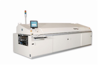
 The Electrovert Vectra wavesoldering system stresses modularity beginning with a fluxer module in a slide-out drawer to permit quick conversion from one type to another. An interchangeable preheater permits conversion from radiant to convection by sliding out and exchanging panels.Photo courtesy of Speedline Technologies Inc.
Another "conventional" tenet avoiding reflow of double-sided PCBs for fear that components will be blown off the bottom is also challengeable. A formula for second-side mounting can determine a component's candidacy for such placement:
Cg/Pa
Where C = component's weight in grams and P = total pad area in square inches (g/in2 must be less than 30 for second-side mount). For example, to anchor parts larger than 68-pin PLCCs (e.g., relays, high-mass/low-lead count), most assemblers use an epoxy. In other cases, solders of different melting points can be used. If the bottom is reflowed first using a high-melt solder (less than 183°C), the top can be reflowed using a eutectic solder (melting point = 183°C). With this procedure, the bottomside will not reflow when run a second time.9

By far the greatest single factor in the formation of solder balls (the defect, not the contact) is the type and composition of the soldermask. A mask that is too dark, perhaps with a finish conducive to solder ball formation or a formula not adapted to BGA technology, can spell disaster when coupled with no-clean processing. Early in the 1990s, research on soldermasks and solder balls indicated that a roughened mask, e.g., one brushed before the soldering process, caused fewer defects than an untreated mask. This is because the rough surface made it more difficult for solder balls to adhere to the PCB. Researchers subsequently developed a liquid photo-imageable soldermask (LPISM) with increased surface roughness that eliminated up to 99 percent of solder balls, even in assemblies with fine-pitch and BGA technologies. It can be applied in several ways: screen print, curtain coat, air spray and electrostatic spray.10
- Vertrel XMS
** SIPAD; Siemens AG
 SelectX selectively removes solder bridging from wavesoldered PCBs using a "tuned" force gas-flow technology to eliminate the defects while they are still liquid. It displaces excess solder but will not disturb good solder joints. Photo courtesyof Vitronics Soltec.
REFERENCES1 Charles L. Hutchins, "Process Improvement," SMT, January 1997, p. 18.
2 William G. Kenyon, SMT, February 1997, p. 26.
3 A.H. Premasire, et.al., "A Novel Activator for a New No-clean Solder Paste," SMT, March 1997, p. 50.
4 N. Cox and R. Schedtler, "Reflow Technology Handbook," Research International, Eden Prairie, Minn.
5 W.G. Kenyon and K.T. Dishart, "End Paste Defects with Solid Solder Deposits," SMT, February 1998, p. 56.
6 D.W. Romm and D.C. Abbott, "Lead-free Solder Joint Evaluation," SMT, March 1998, p. 84.
7 J.S. Hwang, "What Can We Expect in 1998?" SMT, February 1998, p. 20.
8 R. Diehm and J.W. Neupartl, "Trends in Wavesoldering Technology," SMT, July 1999.
9 M. Peo, "How Challenging Conventional Wisdom Can Optimize Solder Reflow," SMT, May 1998, p. 108.
10 C. Wall and S. Tibballs, "Eliminating Solder Balls: Soldermask is the Key," SMT, June 1998, p. 66.
CARL WESSELMANN is the senior technical editor for SMT Magazine, 17730 West Peterson Road, Libertyville, IL 60048; (847) 362-8711, ext. 261; Fax: (847) 362-8027; E-mail: carlw@ihspubs.com.
Share on:


